WINGED WARRIORS/NATIONAL B-BODY OWNERS ASSOCIATION
TURN SIGNAL SWITCH REPAIR TECH
text by Sue and Ed George, photos by Sue George
First and most importantly, if you are working on an E-body, NEVER pound on the steering column! There are plastic plugs (sheer pins) holding the upper and lower sections of the collapsible column together and pounding on the column will destroy them!
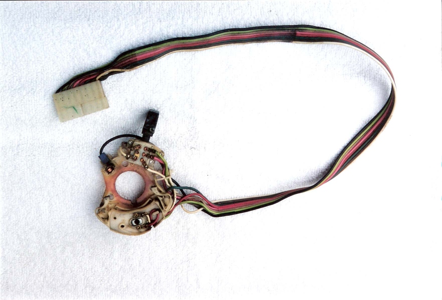
Remove the steering wheel and note where the horn wire connection is located before you pull it out. (If you're working on an e-body, you'll have to remove the corrugated can assembly next). Remove the turn signal lever and the retaining plate, and then it will take some patience to wriggle and pull the switch wiring harness and plug end up through the steering column.
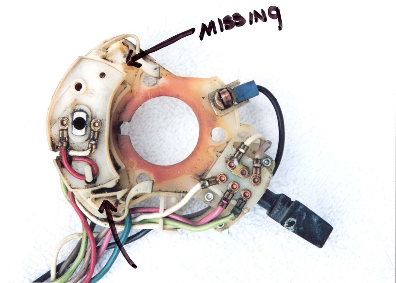
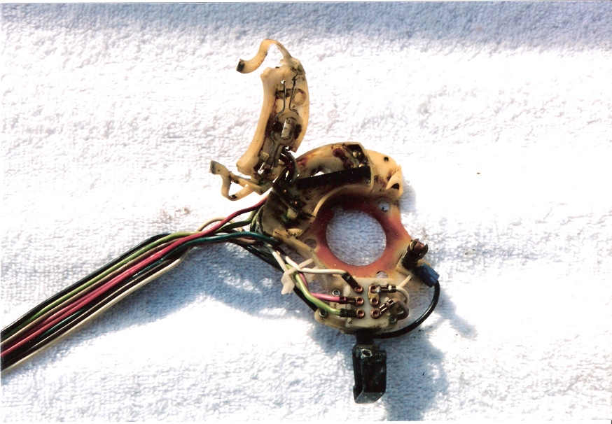
Once you have the turn signal switch and wiring harness removed, it will look like the photo on the left below. The original switch cancel cam mechanism is made out of white nylon. What commonly happens to the turn signal switch is that one or both of the little tangs that hold the signal arm, break off. This requires you to have to hold the signal arm up or down for a signal. You can see the broken off tang in the photo on the right below.
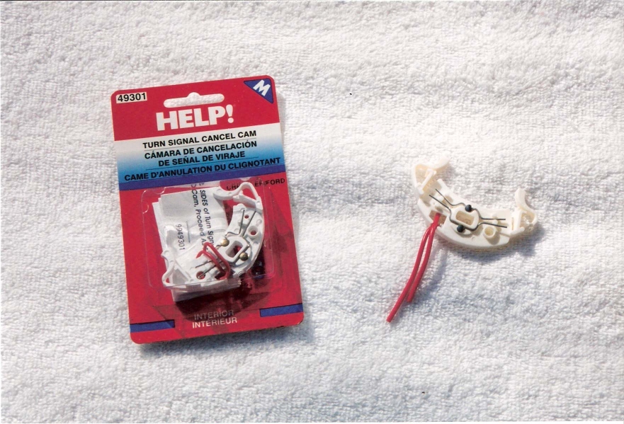
There are two turn signal switch cam repair kits currently available. The one shown above on the right is found in the "Help" items. Most larger auto parts stores have a large display of "Help" items hanging in blister packs. The correct one for 1970 B-bodies is part #49301 and the list price is approximately $19.. Borg Warner also has the same signal cam repair available for 1970 B-body with the part number DR5 without tile wheel and the list price is approximately $20. The Borg Warner part for cars with a tilt wheel is DR.
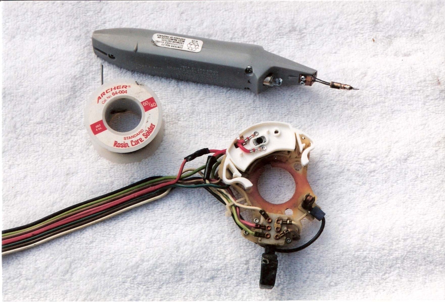
The instructions included with the repair kits are very generic. You will need a soldering iron, and solder as shown at left below, as well as wire cutters and electrical tape or shrink wrap. The new cancel cam is installed in the photo with the necessary tools..
First you have to remove the old cancel cam from your original switch. Using a knife or small flat tool, placing it between the cancel cam and the switch body near the pivot point (near the center), gently pry the two pieces apart. Be careful not to remove all the dielectric grease from the old switch as these kits don't supply any new grease. The old cam assembly is shown at right above, after removal but with the wires still attached.
Hold the new cancel cam up to your old unit and determine which one of the wires goes to the left side and which to the right side, as these need to be soldered to the old wiring harness in the same positions as the original wires are.
Both of the wires on the new cancel cam are red. Holding the new cam in your hand in the same position as the photo above shows, the top wire goes to the red wire on the old harness and the bottom wire goes to the white wire.
Gently snap the new cancel cam onto the switch pivot pin. Feed the new wires down through the slot in the side of the old switch body. Now you're ready to measure and cut the wires to length. Cut the original wires and the excess wire off the new cancel cam so, after soldering, you end up with the wiring harness the same length as it was originally so that it will fit back into the steering column.
Solder the new cancel cam wires to the old harness wires and then tape or shrink wrap the connection. You are now ready to re-install the repaired switch back into the steering column.
TURN SIGNAL SWITCH/4-WAY FLASHER COMPARISON
In the event that the turn signal switch has shorted out or has developed some problem other than the cancel cam having a broken tang, it will be necessary to replace the entire turn signal switch with a new assembly from Chrysler. The Chrysler part number for a 1970 B-body is 4293102.
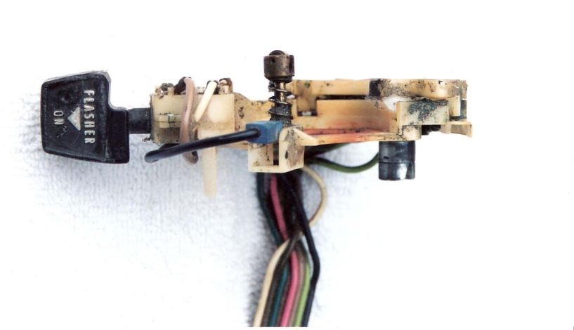
The 4-way flasher knob on the replacement turn signal switches available from Chrysler and the aftermarket parts stores is slightly different in appearance from the original switch. Shown on left below is the original 4-way flasher knob with the words "flasher" and "on" accented in white with a white arrow pointing outboard of the steering column.
Shown below on the right is the new replacement switch that is currently available. The word "flasher" is embossed into the black knob but it is not highlighted with white. Note that the arrow also points towards the steering column rather than away from it.
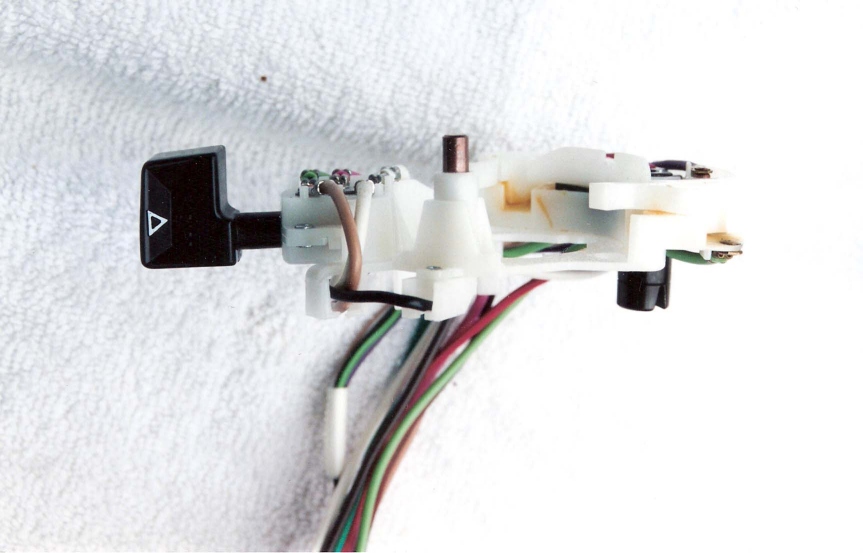
Also note there is a
slight difference in the shape of the knob and stem. It does not quite clear the
slot in the steering column so it cannot be pushed in and pulled out to activate
the four-way flashers. During installation of the new switch, you either have to
file a fraction off the plastic knob (be very careful as it will easily break)
or better yet, file a bit off the slot in the steering column. As long as
your switch does not have an electrical failure and the problem can be diagnosed
as a broken cancel cam, you can retain the original flasher knob by just
rebuilding your original switch with the cancel cam kit.
| MAIN PAGE | TABLE OF CONTENTS |